UnofficialBMW.com
Adding an OBC to an E36 3-Series
ADDING AN OBC
TO AN E36 3-SERIES
This is the second of a two part article
on adding an OBC to an E36 3-series. The first
part explained how to
add European-style parking lights, which is a natural project to
combine with this one since it shares much preliminary work and because
the car needs a different turn stalk if you wish to use it control the
OBC.
An On Board Computer (OBC) can be a useful and amusing accessory, and
in many parts of the world you can order one on any BMW you might
consider. In the United States, however, an OBC is often not an option
until a car has at a least six cylinders. No doubt there are many
owners of 3-series limousines, coupes and cabriolets who would like to
have an OBC, an option that is technically feasible.
This article shows how to add an on board computer to a U.S. market,
standard body E36 3er that did not come with one. The instructions have
been checked against cars built in 1995 and 1996, but likely apply to
early and later model years with possible modifications. The
retrofitting requires some mechanical and electrical skill and probably
should not be attempted unless you are comfortable modifying your car's
electrical system. If the quality of the work is not at least as good
as the factory's, you may have to pay for the consequences should
something later go wrong. The job is not very involved, however, so the
cost of having a journeyman do the work should not be too high.
These instructions assume your car already has an outside temperature
display. They explain how to wire up an OBC to provide most of its
basic functions, everything but check control, the CODE function, and
parked car ventilation. Enabling these functions takes more
effort. The adventurous can consult the Electronic
Troubleshooting Manual for the appropriate year, chiefly section
6581.2. Be warned that the drawings have a fair number of errors and
that it pays to compare ETM's for other model years and other markets.
These instructions draw on the U.S. and German ETM's for 1995 and 1996.
As in previous article about parking lights, the information in this
article has been segregated into two parts: a set of specific
instructions for retrofitting an on board computer and a collection of
more generally useful notes that explain the instructions. The notes
are numbered, and the instructions cite them as they become useful as:
$2.1, $2.2, .... To save space, the instructions also cite note's from
the European parking light article as:
$1.1, $1.2, ....
PARTS LIST
Quant.
|
Item
|
1
|
On board computer (GB/USA), BMW
65 81 8 357 684
|
3
|
Comb terminal contact sleeves
for 0.35-0.5 mm2 wire, BMW P/N 61 13 1 387 140)
|
1
|
Wire end with contacts for
(brown) Siemens socket connectors, BMW P/N 61 13 0 005 201 (part of
Repair Set H, Cartool BMW 61 9 058)
|
6
|
Wire ends with contacts for
(black) AMP socket connectors, BMW P/N 61 13 0 005 197 (part of Repair
Set H.) |
1
|
18 pin AMP socket connector
assembly consisting of: a black contact housing, BMW P/N 61 13 8 364 666,
and an unkeyed water green strain relief shell, BMW P/N 61 13 8 364 662 |
1
|
OBC turn stalk that matches the
car* (see $1.1) |
1
|
wired 2.5 mm round male contact
for 0.5-1.0 mm2 wire*, BMW P/N 61 13 0 007 449 |
(*) You may omit the starred items if you do not wish to
install an OBC turn stalk. The stalk allows you to cycle through the
OBC modes as discussed in the owner's manual. A survey of BMW-digest
readers found a nearly even split between those who really like such
stock control and would add it to their next car and those who find it
useless and would omit it.
Along with the usual tools, you will need a Torx T20 driver to remove
the instrument cluster ($2.2), a long thin T10 driver to run wires to
the fusebox ($1.12) and a 16 mm socket and a thin T25 driver to remove
the steering wheel and airbag ($1.8).
PROCEDURE
1. Read
out any DME fault codes and then disconnect the battery. BMW recommends
you read the codes but this is not crucial.
2. Remove the outside temperature display ($2.1). Unclip the storage
compartment underneath and push it to the right.
3. Remove the driver's kick panel and knee protection ($1.7).
4. Lift and unclip the black terminal/relay block on the front left
wall above the driver's footrest (parking
light article, step 4). Rotate the block so that you can add to its
wires.
5. Remove the steering wheel and airbag ($1.8).
6. Remove the instrument cluster ($2.2).
7. If you are installing an OBC turn stalk, change the turn stalk and
remount the four steering column connectors ($1.2).
8. Construct and lay the supplementary harness (later section and $2.5).
9. With the harness in place, move the following wires from the
original temperature display connector to the new OBC connector:
Move
|
Wire Color
and Function
|
To
|
| X1070
pin 17 |
0.5 mm2
brown ground wire |
X1071
pin 13 |
| X1070
pin 18 |
0.5 mm2
red/yellow B+ wire from F31 |
X1071
pin 8
|
10. Reassemble connectors X1070 and X1071 and tidy up the wiring. The
new X1071 connector is unkeyed and will fit the wrong socket on the
OBC. To make sure of what it is going into, first plug the black
connector, X1070, into the black, passenger side socket; then plug
X1071 into the natural-color, driver side socket.
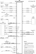 This
schematic summarizes the conversion.
This
schematic summarizes the conversion.
11. Clip the terminal/relay block back on to the left wall. Reinstall
the instrument cluster, steering wheel and airbag ($1.9). Make sure no
one is in the car and reconnect the battery.
12. Turn the ignition key to position one, the accessory position. A
brand new, uncoded OBC will display P
P P P. You now need to visit the dealer and make use of their
DIS computer. First have the dealer run diagnostics on the OBC. You may
see the following faults:
Central
check control light
Gong
T2
Gong
T1
Code-Function
Timer
Terminal
50
All
these “faults” are normal: the first if the car doesn't have check
control, the second and third because you disconnected them, the fourth
because you have not connected the drive-away protection, the fifth
because the car doesn't have parked car ventilation, and the last,
because you did not connect the OBC to the starter motor, assuming you
constructed the suggested harness. (If you decide to add parked car
ventilation or the CODE function, be sure to make the connection as
shown in the ETM.)
13. If your wiring checks out, have the dealer code the OBC and place a
new central code sticker under the back seat bench. A Meister may tell
you that this is impossible. Actually, it is just a little uncommon,
and a matter of finding the right menu. Then road test the OBC. At the
very least, verify the CONSUMption, TEMPerature, SPEED and RANGE
functions, and the turn stalk switch if you have added it. Once you are
satisfied everything works, reinstall the knee protection, the
diagnostic connector, the driver side kick panel with chimes and the
steering column shrouds.
Enjoy your on board computer.
ACKNOWLEDGEMENTS
I would like to thank Thomas Fiebig (Bobrink GmbH), Allan Rhodes,
Jr. (Bluegrass Honda/BMW), Ron Stygar and Terry Donohue for
providing parts and practical information that made the OBC conversion
possible.
SUPPLEMENTARY HARNESS
1. ADD A WIRE to X1070 pin 9 only if it missing. If you are
adding parking lights or do not mind running a wire to the fusebox ($1.12),
wire:
X1070
pin 9
A-------.5 mm2 GN/BL------[ X1076
Otherwise:
X1070
pin 9
A-------.5 mm2 GN/BL------* X17 pin 4
2. IF YOU WISH to control the OBC from the turn stalk, wire:
X1071 pin 4 A------.35 mm2
BR/RT------R X32 pin 10
3. IN ALL CASES, wire:
X1071 pin 5 A------.35 mm2
WS/VI---------------------[ X183
X1071 pin 6 A-------.5 mm2
WS/SW------* X16 pin 21
X1071 pin 7 A------.35 mm2
WS/GE---------------------[ X182
X1071 pin 9 A------.35 mm2
WS/GR------S X17 pin 10
SYMBOLS AND WIRE COLORS:
A - AMP contact
($2.4)
BL blue RT red
R - 2.5 mm round male contact
($1.4) BR brown SW black
* - Splice to wire
($2.6)
GE yellow VI violet
S - Siemens contact
($2.4)
GN green WS white
[ - Contact sleeve
($1.11)
GR grey
COMPONENTS AND LOCATIONS:
X16 is the 26 pin, white connector
you removed from the back of the instrument cluster; you will splice
into one of its wires and possibly a wire going to connector X17.
X17 is the 26 pin, blue
connector you removed from the instrument cluster; you will also add to
it a wire with the one Siemens contact.
X32 is the 12 pin, white, male
turn stalk connector ($1.5).
X182 and X183 are comb terminal junctions in
the left wall relay/terminal block.
X1070 is the 18 pin, black
connector that plugged into the passenger side socket of the outside
temperature display.
X1071 is the new, 18 pin
connector that will plug into the driver side socket of the OBC; it
will take the five or six AMP contacts.
X1076 is a comb terminal
junction in the fusebox.
NOTES
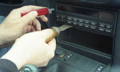
2.1 REMOVING
THE OUTSIDE TEMPERATURE DISPLAY
 .
.
If you have a late model car, feel along the top of the storage
compartment immediately below the display for a hole giving access to a
compressible retaining bar. Press up on the bar to retract its
ears holding in the bottom of the display, and while pressing, pull or
gently pry the display out of the console. If you have an older car,
insert a 1 mm feeler gauge or blade between the top of the storage
compartment and the bottom of the display. Press the bar upward and
carefully pry out the display. Unplug the rear connector as it becomes
accessible ($2.3) and remove the display.
2.2 REMOVING THE
INSTRUMENT CLUSTER
Remove the airbag and steering wheel ($1.8). Remove the two Torx-20
screws that secure the top of the instrument cluster to the top of its
well. Gently pry down the top edge of the cluster until it comes frees,
then slide it out. Be very careful not to scratch its soft, plastic
face; clear plastic will attract all but the most carefully controlled
tool. Unclip the instrument cluster's three connectors as they become
accessible ($2.3) and remove the cluster.
2.3 UNPLUGGING HIGH DENSITY SOCKET CONNECTORS
The connectors are mated and separated with the aid of a swing
lever. Press down on the plastic tab that juts out from the outer
connector shell and locks the lever. Swing the lever over the tab
and away from the vertical. Continue swinging until the lever is
horizontal; then remove the connector. To plug the connector back in,
start with the lever fully horizontal.
2.4 ADDING
AND REMOVING HIGH DENSITY SOCKET CONNECTOR CONTACTS
To access the contacts, slide the black retaining clip off the end the
wires exit; then gently pull on the wires and slide out the slim,
rectangular contact housing. The contacts are numbered. They have
retaining barbs which must be oriented so that they pop into the
windows on the side of the housing; the contacts will then click easily
into place. To remove a contact, use a straightened paper clip, gently
press the contact barb through its window and slide it out. It should
come out easily.
2.5
CONSTRUCTING AND LAYING THE WIRING HARNESS
Try to route the harness so that such things as the air conditioning
can be removed without cutting wires. Someday, you may appreciate your
foresight. You can use plastic ties to add to the car's existing cables
or you can slip wires under the cable tape where it is loose.
Don't worry about having some slack at the ends of the harness: you
will have room and it is better than coming out too short. Try to use
the indicated wire sizes and colors ($1.3).
You can now add wires. The contact locations are numbered and can be
read with a bright light. To add a wired contact, find the correct
position, thread the wire through the retaining shell and then click
the contact into the contact shell. Remember: through the retainer;
then into the shell. Don't forget or you may have to beg your dealer to
lend you their contact removal tool.
2.6 SPLICING
INTO EXISTING WIRES
 .
.
In the instructions they supply with their aftermarket products, BMW
cautions: “Never use Scotchlock
fast connectors”, as they may cause
faults in low-level electronic signals. Here is a more compact and
reliable way to splice into existing wires, for example, the B+ and
fuel consumption wires running to the instrument cluster.
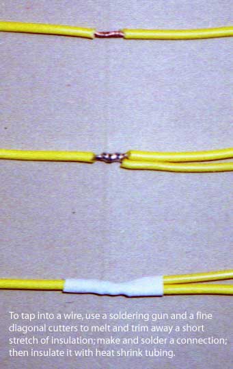
Find the wire you wish to tap into and unplug it from its connector.
Unthread the wire from its harness back to the desired tap-in point.
Using a soldering gun (but probably not its tip), melt through the
insulation on both sides of the wire trying not to heat the wire very
much. Bow the wire with your fingers and separate it from the melted
insulation.
Using a fine diagonal cutters, pull back and trim away the melted and
softened insulation so that you expose a short section of bare
wire. Lay the new wire alongside the original, wrap it around the
bare section, solder the connection and insulate it with heat shrink
tubing or electrical tape (Fig. 2). Then plug the original wire back
into its connector.
Copyright © 1997, 2001 and 2009 by
John
Firestone