| Quant. |
Item |
|---|---|
| 1 |
European-market turn stalk with parking light switches (see $1.1) |
| 3 |
Comb terminal contact sleeves for 0.75-1.0 mm2 wire, BMW P/N 61 13 1 387 142 |
| 3 |
2.5 mm round male contacts for 0.5-1.0 mm2 wire, BMW P/N 61 13 1 376 191 |
| 3 |
short pieces of 0.75 mm2 wire, six feet each will suffice: one grey/violet, one grey/yellow and one red/white ($1.3) |
| X32 pin 2 |
grey/violet (GR/VI) |
| X32 pin 7 |
grey/yellow (GR/GE) |
| X32 pin 12 |
red/white (RT/WS) |
 .
.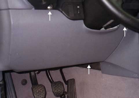 .
.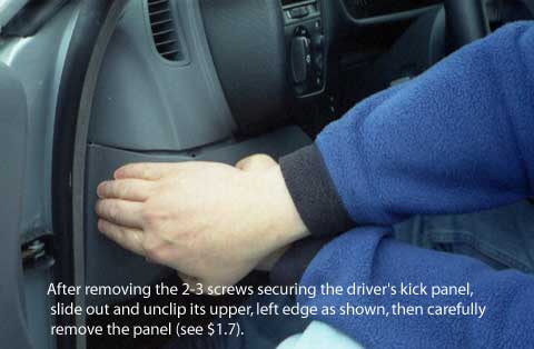 The top edge screw will be underneath a small, plastic,
D-shaped cover. Save the screw with its cover. Unclip the panel from the left end of
the dash, by sliding its left edge toward the back of the car and gently
pulling it out a little.
The top edge screw will be underneath a small, plastic,
D-shaped cover. Save the screw with its cover. Unclip the panel from the left end of
the dash, by sliding its left edge toward the back of the car and gently
pulling it out a little. .
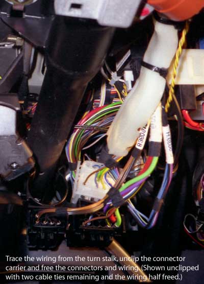
.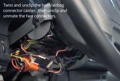 . Unclip the flat, white/black
connector pair from the carrier and unmate the connectors ($1.10).
Separate the round, orange/grey connectors as well.
. Unclip the flat, white/black
connector pair from the carrier and unmate the connectors ($1.10).
Separate the round, orange/grey connectors as well.