|
Ron Stygar Carl Buckland Dale Beuning Forums Help
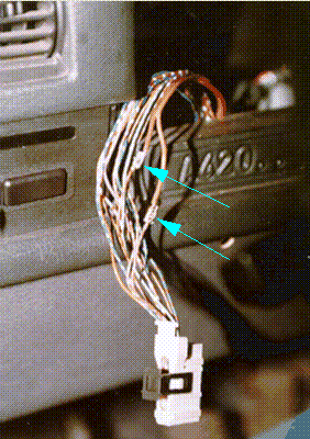
Detailed diagnosisThis page details the troubleshooting I did to determine the fix for the speedo. When the speedo went bad I had an opportunity to have a shop replace the sensor with a known good one. They did this for me and found no difference in the behavior of the speedo. This ruled out a bad sensor. I removed the instrument cluster and removed the speedo unit and carefully looked over all aspects of it looking for a problem and I couldn't find any. I left the speedo non-functioning for nearly two years before joining the mailing list and reading about others with the same problem. I decided again to attempt to repair the faulty speedo. What I was noticing is that it would work intermittently, but then usually die again soon. My initial thoughts were that the exposed portion of the sensor wire had aged and cracked, causing an intermittent connection. I traced the sensor wires from the speedo sensor to where they enter the car. This is under the rear seat on the passenger side. I removed the wires from the sensor, cut, and soldered new wires to the old, and pulled these through the protective sleeve into the passenger compartment. I then soldered them to the existing wires. Took the car for a drive, and no speedo. The wires were attached to each other like lamp cord ( zip-cord) one was brown ( the ground ) and the other was brown with a red stripe ( the signal ). I decide to trace the wires through the car to determine if there was a break somewhere. The wires proceed from the rear seat along the passenger side rocker panel and then turn towards the drivers side of the car right in front of the passenger front seat. From there, they head about two inches forward of the shifter, in front of the drivers seat and to the drivers side rocker panel. They then head towards the wire bundle in the front at the fire-wall. From there, they go towards the instrument cluster white connector. About 4 inches before the connector, the wires are crimped to the smaller wires used with the connector that mates with the instrument cluster. I used these crimp connectors as a test reference point for determining if the speedo unit was functioning properly. The teal arrows in the picture below show the location of these crimp connections.
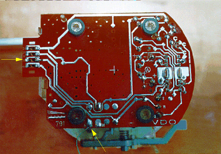
I used a fluke 87 DMM attached to these connectors to monitor the speedo signal both in the garage and while driving. What I noticed during driving, was that there was a frequency associated with speed, but the numbers I was getting didn't make sense and the speedo was not working at the time. I talked to some electrical engineers and they suggested that the speedo needs to be powered to work properly, so the signals I was getting were mostly noise. This narrowed the problem to the fact that the speedo sensor was not getting power. This lead me to look closely at the instrument cluster and all the connections the speed signal makes with the instrument cluster. I pulled the speedo unit out and pushed the spring type contacts on the unit closed to help make a better connection. When I had the speedo unit out, I noticed that some of the solder joints looked as if they had been touched up. The explanation for this is that these joints are what hold the speedo circuit board to the speedo unit. I re-flowed these joints and put the speedo back. I took it for a test drive and it worked for a short time and died. After some discussions with Bryon Pinkston ( pinkston@aros.net), He told me about the lead for the cruise control from the back of the instrument cluster behind the speedo unit. I decided to move my test point to this contact on the back of the speedo in an attempt to get closer to the origin of the problem. I took out the speedo unit and soldered a wire to the cruise output signal. At that time I also decided to re-flow all the solder joints on the speedo circuit board. I put the unit in and hooked up the DMM and took the car for a ride. The test point is shown below with a yellow arrow on the bottom of the picture.( notice the green test wire) and the speed input from the sensor is the yellow arrow on the left in the picture.
It worked!!! I turned on the DMM and checked the frequency, it was roughly twice the vehicle speed. ie at 20mph it read 40 Hz, at 60 mph it read 120 Hz ...etc. The voltage across the wires was about 7.5-8.5 Volts DC ( if I recall correctly). I left the setup connected for a couple of days and in the mean time told Bryon about the re-flow procedure. He did the re-flow to his speedo unit, and it fired to life. I think the problem is solved. as of writing this I have about 1000 mi on the fix through rain, cold weather, bumpy roads... and it still works fine. Back to the speedo repair page. Jeff Schnellinger jms_at_kistler_dot_com |


