|
Ron Stygar Carl Buckland Dale Beuning Forums Help
From RonStygar_at_aol.com Thu Jun 5 10:51:07 1997 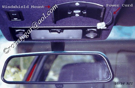
The following describes how I mounted and hardwired my Valentine (V1) Radar Locator (non-laser) in my '96 328is and '97 318tis.
            Parts:
                      In-line fuse assembly:  Radio Shack 270-1238 $ 1.59
                      Spare 1A 250v fast-blo fuse: Radio Shack 270-1049 $1.99/4
                      Red and blue tap-in connectors, ty-wraps, tape etc.
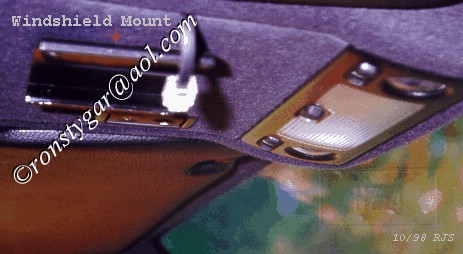
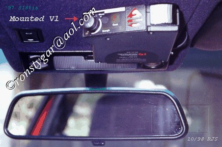
Referencing the FAQ and various posts I decided to mount my (V1) on the BMW removable panel above the front interior and map lights. There are many ways to do this. This is how I did it. It may sound complex, but it really isn't. Although Velcro was suggested, it just didn't look right, and the angle wasn't right. Using the (V1) visor mount, I removed the visor clip from the mount and screwed the remaining mount to the removable BMW panel. This BMW panel retails for $11.54, so if you want to go back to stock it is no big deal. Remove the sun roof switch using your fingernail pulling down at the ends. Remove the panel by sticking your finger in the switch hole and working it out. I drilled two holes in the (V1) mount ends, at the top of the arc to accommodate 6/32 pan head machine screws cut to the proper length. Using the (V1) mount as a guide transfer the holes to the BMW panel. I favored the passenger side of the panel. Be aware of which end is up, before you drill. All the following measurements are from the edge closest to the front interior lamp and the passenger side edge of the panel. In my case hole #1 measured 2 1/4" - 2 1/8". Hole #2 measured 4 3/16" - 2 5/16". I filed a notch on the passenger edge to accommodate the 4 wire phone cable. This notch is 2 5/8" from the front edge. To accomplish this I pulled back the fabric at this point. I filed the notch and reglued the fabric. Mount the (V1) bracket on the panel with the nuts on the inner side of the panel. This will prevent scratching the top of the (V1) when installing or removing it. There is no reason to use the (V1) Direct wire power adapter if you are aware of which pin is +12 and which pin is ground. Using the adapter makes it idiot proof. The above was verified by a call to Valentine. Take the straight power cable that came with the (V1) and hold the connectors side by side with the locking tabs up and the pins facing away from you. Look closely and you will see that the color sequence left to right is yellow green red black on one and black red green yellow on the other. If you use the later sequence red will be +12V and green will be ground. If you use the first sequence green will be +12V and red will be ground. I chose the latter sequence. When plugged into the detector the red wire will be toward the rear of the detector. In this case red will be +12V and green will be ground. If your not sure of what is going on here, use the adapter. I cut the cable using the above end to a length of 7". I cut back the unused black and yellow wires. I spliced the red wire from the Radio Shack in-line fuse assembly to the red wire of the phone cable. I spliced a brown wire to the green wire of the phone cable. Install the 1A fuse that came with the (V1) unit in the in-line fuse assembly. Remove the map light assembly by pressing it out at the openings edge. For my ‘97 318tis (in the area above the panel) I connected the fuse assembly red wire to the .5 VI/WS violet/white wire feeding the map light assembly. This is pin 1 of connector X336 (which is in the same area) and is hot in accy, run and start. Connect the brown wire to the .75 BR brown wire pin 4 of the same connector. Although the Electrical Troubleshooting Manual shows it to be different, I found it to be the same for my ‘96 328is. The only difference with the 328is is that you must reinstall the panel prior to the map light assembly. Reinstall the BMW panel leaving enough of the phone cable sticking out (at the notch) to plug into the detector. I removed the locking tab from the connector to allow quick and easy removal. Using a paper hole punch, I punched out a circle of black electrical tape. I installed this over the detectors photo cell. This dims the indicator lights just enough. Install the detector, plug-in the cable and check its operation. If everything checks out, Good Job! If not, reread the above.
Ron_at_unofficialbmw.com, FLI BMW, FLY BMW, Marlborough, CT |