Installing cruise control in a 1986 BMW 325
By Alex Horvath
ah_at_1877goxray1.com
First off, after having checked on the web, as well as asking on message boards, I found no information on whether it could in fact be done, and if so, what was required.
Second, it’s dead easy. It can be done in a few hours with basic tools and a little elbow grease.
Finally, my car was manual. I took parts from both manual and automatic cars, and as such I saw some differences. I have tried to describe the differences where possible, but I may have left some things out. Search for “automatic” to find specific references. Otherwise, the document assumes a manual car.
Parts List:
- E30 BMW, without cruise control 318, 325, 325i, etc.
- Cruise control servo 65 71 1 386 242.9
- Cruise control servo bracket 65 71 1 386 226
- Cruise control wiring harness
- Cruise control actuating lever 1 370 162
- Cruise control computer/ECU 65 71 1 386 189
- Cruise control computer bracket (optional)
- Clutch switch (optional, manual only) 61 31 8 360 421
- Clutch switch bracket (optional, manual only) 35 11 1 157 815
- Clutch switch bypass (required for automatic)
- Ground lead to attach to wiring harness
- Instrument cluster multi-function plug
- Nuts, bolts, screws for all the above
A description
of the parts, and why you need them:
E30 BMW:
Next.
Cruse control servo:

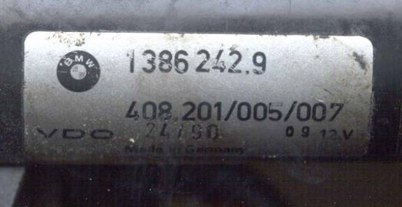
Black plastic box with a motor mounted on it. Has two cables coming out of it, one with a grommet and a 7 pin electrical connection on the end, the other with a linkage identical to the one that is used for the gas pedal cable/throttle arm.
Used to keep the throttle in place while cruise is on. Controlled by the ECU.
Cruise control servo bracket:
This is the first thing that is somewhat confusing: There are two types of brackets. The one that you will most likely see is the one for factory equipped models. It has three M5 studs coming out of it that match the holes on the servo. It has two holes in it that mount to the studs in the engine compartment above the driver’s side wheel well. If you’re reading this, you probably don’t have cruise already on your car, and probably don’t have the studs either. That’s what the second type of bracket is for. The second type has the same studs as the first, but instead of being mounted to the body above the wheel well, it has holes so it can be mounted to the air filter box mountings.
This is the ONLY part that I was not able to find. BMW has no record of it, but it is a BMW part. See pictures for more information. (Sorry, no pic yet. I really need a digital camera!)
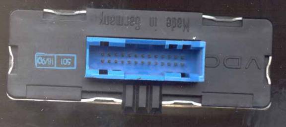
Cruise control wiring harness:
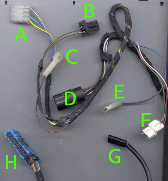
Cables for connecting the electric and electronic parts together. It consists of the following connectors (letters correspond to plugs on picture):
A) Actuator Lever Connection
B) Clutch Switch Connection
C) Ground Connection
D) Servo Connection
E) Unknown, possibly transmission switch for automatic (connects to a relay) Automatic only
F) Brake Switch Connection
G) Speedo Cluster Connection
H) ECU Connection
NOTE: There are two versions of this harness. This is a picture of the harness 12/87 and BEFORE. The other harness is not compatible with cars with this date or before, and this harness is probably not compatible with cars produced after that date.
Cruise control actuating lever:
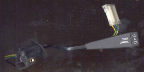
Turns the cruise on and off, sets and resumes speed. Looks like the windshield washer lever, but has cruise commands on it.
Cruise control ECU:
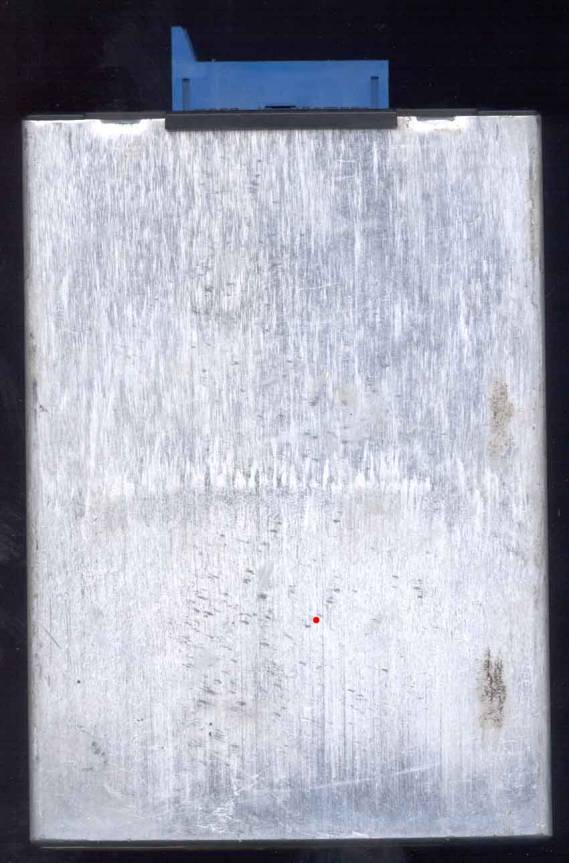
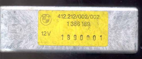
Big, silver box with 6 sides. One side has a connector on it, this is important. The box controls the servo based on the speedo connection and the actuator lever. This is the brain of the system.
Cruise control computer bracket:
I’ve never seen one, and it’s not really needed. It holds the computer in place next to the engine management computer.
Clutch switch:
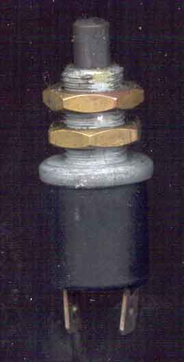
Cylindrical push-button switch with a button and some threads on one side, and two male spade connectors on the other. It screws into the bracket (below). Used to disengage the cruise control when the clutch pedal is depressed. Above picture is of a brake switch, the clutch switch has a read pushbutton. The clutch switches I have seen have all been stuck in the IN position. This means that the cruise will work all the time, regardless of the clutch position, and will not disengage if the clutch is depressed. I freed mine by spraying WD-40 on it and tapping it gently with a piece of wood.
Clutch switch bracket:
Small metal bracket that holds the clutch switch in place.
Clutch switch bypass:
Connector that takes the place of the clutch switch on automatic models. It’s just a bridge that makes the computer think the clutch switch is always off.
Ground lead to attach to wiring harness:
Brown wire with M6 lug on one end, and a plug that fits wiring harness plug “C” on the other. Used to provide 0VDC to the system.
Instrument cluster multifunction plug:
The ones I have seen are green. They plug into the back of the instrument cluster. They provide a place to plug wiring harness plug “G” into. Provides the speedometer pulse to the ECU.
Nuts and bolts:
Keep the originals and re-use them. If you have stainless steel equivalents in your shop, you can use those also. All the parts I removed from the inside of the car looked like new, and the exterior parts were all in good enough shape to re-use.
Getting
the parts:
I got the parts (except the bracket) at the local wrecker (OK, so it wasn’t local, but it WAS a wrecker, and I was able to get to it). First make sure they have some BMWs. E30s and E28s (up to ’88 528e, 533i, 535i) are both good, but I think you need an E30 harness, not because of the connectors, but because of the length. Make sure YOU get the parts, not the guy in the pickup truck with the hoist on the back. You’ll be a lot more gentle, and this way you can see where it came from so you know where it goes (even though I’ll tell you, it’s still better to see for yourself). Also, as stated before, make sure the harness you get fits your car. I got one from a mechanic that wasn’t right, and I couldn’t figure out how to change it to make it work. Even if you can change the connectors and figure it out, it’s easier to just get the right harness.
Cruise control servo:
On the E30s, it’s mounted above the driver’s side wheel well in the engine compartment. Before we dismount it, we’ll free up the cables.
The control cable is routed along the driver’s side of the engine compartment, and enters the passenger compartment through the firewall under the fuse panel. To get to the connector, you have to remove the knee panel. This is done by turning the screws at the top of the panel, and where the panel meets the steering column, 90°. Remove the knee panel by pulling towards you. Once the panel is off, look down by where the rest of the wiring goes through the firewall and you’ll see the cable coming from the servo (D on the wiring harness picture, C on the servo picture). Disconnect the cable, and gently push it, along with the grommet, back through the firewall.
Next we’ll disconnect the throttle cable. This cable is routed along the driver’s side shock tower to the throttle arm. There is a cable guide bolted to the shock tower (not shown, I didn’t take it), take this if you want, but you can just tie it off later and not have to worry about undoing another bolt on your car. There is a plastic insert (A) that clips into a bracket (not shown, but you can’t miss it, it is what part A is plugged into. It is held onto the engine with an M6 bolt) to hold the cable’s jacket to the engine. This insert gets brittle with time, and will likely break if you try to take it out (the picture shows a broken one). Don’t bother trying to take it out right now, take the insert and the bracket together, and take the insert out later. Once that is off, you have to unscrew the locking nut on the end of the threaded rod (B4). This is the one place where corrosion causes problems. The nut is small (M3, I think) and it rusts onto the threaded rod. If it won’t come off, see if you can get some WD-40 to help it out. Not a big deal if you have to destroy the nut, just be careful with the threaded rod. You can get another nut from another car or buy one somewhere else. Once the nut is off, unscrew the adjuster (B2). You can now pull the cable out. Watch out for the little metal piece that it goes through (B3), it’s held in place by the cable, and can fall out when the cable is pulled out. Once the cable is out, GENTLY remove the plastic insert (B1) that holds the cable. This is brittle too, but it doesn’t need to be bent as much to remove, so it probably won’t break.
Before you do anything else, reassemble the end of the cable by passing it through the little metal piece in the insert, and screwing on both the adjuster and the nut.
Finally, we’ll remove the servo. Unscrew the three M5 nuts using a socket, and pull the servo off. Put it in a safe place. Replace the nuts on the bracket.
Cruise control bracket:
Remove the bracket by taking the bolts off the two studs on the body. Keep the nuts.
Cruise control wiring harness:
Before we remove the harness, we have to do a few things.
The steering wheel HAS to be off. There are a few ways to do this, the easiest being to remove the steering wheel center, unscrew the large nut, turn the key to disengage the steering lock, and take the steering wheel off. This method is often not possible since there are rarely keys in the wrecked cars. The second easiest way is to take the nut off, and kick the wheel from the outside, through the windshield opening, until it comes off. This will damage the wheel, and the windshield if it’s still intact. Alternately, you can remove the nut and go nuts with a large crowbar or similar tool. The wheel will eventually come off, but it’s not easy. You can also try prying the lock (clockwise, all the way), but this is also difficult.
Once the wheel is off, remove the lower steering column trim (4 phillips / pozidrive screws, M5, two at the wheel, two in the well by the end of the trim). Next, remove the instrument cluster. Reach behind the cluster and find two (one on each side) M5 thumbscrews that hold the small piece of trim between the top of the steering column and the bottom of the cluster. Unscrew these and push the studs that they were on outwards, the trim will pop out towards the seat. You now have access to the cluster bezel, which is held in place by four black Phillips screws. Once the bezel is off, the cluster is held by two silver Phillips screws. Once these are removed, the cluster can be tilted forward from the top to be removed. Note, if the cluster is in good condition, place a rag on the steering column so the cluster glass doesn’t get scratched (you never know, since it’s out, you might want it as a replacement).
Next, open the glove box. Remove the pins from the straps that hold it up, so you have more room. Remove the computer cover turning the screws 90° and pulling out. There is another cover that covers the driver’s side of the glove compartment. Remove this too. There is a tricky thumbscrew hidden behind one of the computer cable bundles. You’ll find it when you’re in there.
Having done all that, you can now remove the ECU and one side of the harness. Pull the ECU out along the top of the compartment towards the driver’s side, then tilt out towards the seat. One it is out, pull the black tab on the blue connector to unlock it, and pull the blue connector off.
This part is tricky. If you have long, slim arms you can possibly unclip the cable ties behind the radio that hold the cruise wiring harness. For the rest of us, remove the radio and do it that way (note, and M2 or 2.5 allen key will open the 5-sided socket screws that holds the radio in place).
Next, move to the driver’s side. Cut the cable ties that hold the cruise harness to the rest of
the cables, and follow each wire to its end.
LOOK! You’ll have a much easier
time if you look where the cables go and make notes than if you have to refer
to my descriptions! MAKE SURE TO
MARK THE LOCATIONS OF THE BRAKE SWITCH (GREEN/RED + WHITE/PURPLE) AND SPEEDO
PICKUP (BLUE/YELLOW).
The plug locations are as follows: The speedo pickup plugs into the back of the green multi-function plug (see below). I don’t know offhand which pin it is connected to, but it is on one side and it is keyed. When you take it out, mark it. The brake connector is all the way at the front left part of the driver’s side foot well. There is a connector block there, and it plugs into the farthest part of the connector. Both connectors are keyed, so as long as you’re in the general area, you shouldn’t get it wrong. If you got the wrong harness, this is irrelevant because it simply won’t fit into your car no matter how much you write down.
Disconnect the harness, one connector are a time. Once all the connectors are disconnected, pull the harness through to the driver’s side through the cluster opening. Once that’s done, feed the harness down through the small opening by the driver’s side air vent (if you didn’t cut all the cable ties yet, you have to do it now). Once the blue connector goes through, it will drop to the floor and you’re done! Coil the harness up and store in a safe place.
If you have an automatic, this may apply to you: There is a connection from the wiring harness that connects to a relay mounted on the steering column on automatic cars. I think this is for the neutral disconnect switch, but I don’t know. The only reason I mention this is because my harness came from an automatic, and I didn’t know what to do about the relay until I looked in a manual car and saw that there was no relay.
Cruise control actuating lever:
Don’t worry, this one is really easy. Slide the actuator connector out from the rest of the connector bundle, and let it hang loose. Remove the M5 phillips screw that holds the windshield wiper control lever. Remove the actuator arm and replace the screw. This screw is VERY important, you WILL need it later! Put the lever AND the screw in a safe place. If you need a washer or turn signal lever, you might as well take one now, since they’re both exposed.
Cruise control ECU:
You didn’t just throw it away after removing the harness, did you ? OK, go find it and put it in a safe place.
Cruise control bracket:
If there was a bracket holding the ECU, remove it, put the screws back in it, make a note of where the screws went, and put it in a safe place. If someone out there has one and is willing to take pictures, please let me know and I’ll add to this part.
Clutch switch & Clutch switch bracket:
This is probably the most difficult step, and for what you get, I don’t think it’s worth it. Still, here’s the description. The bracket is bolted to a support that is directly between the brake and clutch pedal stalks. This makes it extremely difficult to remove. If you can, get someone to hold the brake pedal back with a long pole so you can access the M6 bolt (M10 socket) to remove it. I took it off by bending the tab that prevents it from rotating, and rotating the entire bracket and holding the bolt. Lots of cursing was required to get it off this way. The switch is in the bracket, and is probably seized. Leave it for later. Make sure you keep the bolt, screw it back into the bracket, and put it in a safe place.
Clutch switch bypass:
Automatics (or standards who don’t want the hassle of getting the clutch switch & bracket): Remove the bridge connector from the floor where it fell after you disconnected it from the wiring harness and put it in a safe place.
Ground lead to attach to wiring harness:
Unscrew the bolt holding the all the brown wires to the chassis. One of these wires will be the one that you disconnected from the wiring harness. Take this wire out from the bundle and reconnect it to the wiring harness. Note the location of the screw so you can re-attach the wire on your car.
Instrument cluster multi-function plug:
Look at the back of the cluster. See the green connector that the blue/yellow wire was plugged into. Pull it out from the cluster (it attaches from the bottom, so pulling out is down). Since you probably remember where you pulled the blue/yellow wire from at this point, it is a good idea to mark it. Put it in a safe place.
Count your tools, re-read this document, compare your parts to the list at the top, and pay. I got my parts for less the $50CAD ($35USD).
Installation:
Installation is the same as removal. Well, almost. Here are some key differences:
The servo bracket may not fit on your car, since the car may not have the studs for it. I’m working on a drawing for a piece of metal for a modified bracket that will mount to the air box.
You will have to cut out the rubber grommet in your firewall to pull the control cable through. Measure the grommet on the control cable TWICE, then using a sharp knife, cut a hole a little smaller than you need. Enlarge as necessary. When you pull the cable through, seal it with silicone caulking to ensure a watertight seal. DO NOT cut out the biggest hole. I did this, thinking it would fit. It doesn’t, and I had to make an adapter to make the grommet on the cable bigger.
Use a pair of channel-lock pliers to remove the insert for the throttle cable from the bracket. Be very gentle, and you’ll be able to get it out without breaking it. Also be careful when you put it in. Once it’s in, it won’t break.
The adjuster (B2) should be screwed on so there is no slack between the pin (B3) and the adjuster (B2). Be careful no to tighten the adjuster too much or it will affect the idle speed of the car (it will keep the throttle from closing all the way)
The lower steering wheel column cover doesn’t have a cutout for the cruise control actuator lever. There is a marking showing where it should be cut, though. Use a sharp knife to cut out the plastic. Sand or file the edges to finish.
The actuator lever won’t screw in properly with the original windshield wiper lever. You’ll have to drill the windshield wiper lever’s threads out (I think it’s a 5.5mm drill) to accommodate the screw you took with the actuator. Not a problem.
Clutch switch bracket installation is a real pain. It’s much easier if you have someone to help. Get your helper to push the brake pedal down with a broomstick from the passenger seat so you have better access to the place where you need to mount the bracket. I put the bracket in first, then the switch.
Once everything is installed, check that it works, then tie wrap everything up nicely. This ensures that next time you work down there, it’s clean.
Final Words:
If you have any questions, I can be reached at ah_at_1877goxray1.com. Put “BMW Cruise” in the subject line for quicker results.
If anyone out there who reads this has pictures for the stuff I don’t have and wouldn’t mind letting me use them, please let me know, and I’ll add the pics and credit the source. Also helpful would be part numbers for the parts that I don’t have them for. Someone with a traditions CD can probably help me out here.
Prepared by Alex Horvath
This document is © 2003 by Alex Horvath, and may not be redistributed without my permission. This file was written to help out those people who, like me, like to work on their own cars. If you wish to publish this document, please email me and chances are I’ll let you do it.
BMW, the BMW logo, BMW part and model numbers, and anything to do with the BMW itself are probably trade marks of Bayerisch Motoren Werke AG, Munchen, Germany. If someone has a problem with the text or pictures because of a trademark issue, please let me know and I will modify the document accordingly.
Revision 1 October 2nd, 2002 Original
Revision 2 March 24th, 2003 Added Pictures, some text.
Revision 3 Same Added smaller sized pictures for web
Revision 4 Same Saved as HTML, final proofread
Revision 5 Same Added some more helpful hints, re-read, proofread again
Revision 6 Same First Public Release